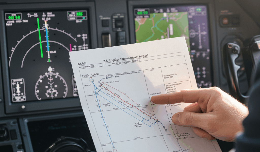
Approach Chart Legend
Understanding the Approach Chart Legend
Approach charts are essential tools for pilots. They provide crucial information for safe navigation. The legend of an approach chart serves as a key to interpreting the various symbols and data points. Here, we delve into what each element of the legend represents.
Runway Information

- Runway Numbers: These indicate the magnetic heading of the runway. For example, 09 denotes a heading of 090 degrees.
- Runway Length: Denoted in feet or meters, it indicates the total length of the runway available for landing and takeoff.
- Runway Lighting: Symbols indicate the type of lighting installed, such as Precision Approach Path Indicator (PAPI) or Instrument Landing System (ILS) lighting.
Navigation Aids
Navigation aids (navaids) are critical for guiding aircraft. The legend includes several symbols denoting different types of navaids:
- VOR (Very High Frequency Omnidirectional Range): Represented by a hexagon, it provides azimuth information to pilots.
- ILS (Instrument Landing System): Depicted with a vertical triangle. This provides both horizontal and vertical guidance.
- NDB (Non-Directional Beacon): Shown as a circle. It transmits signals with no directional information, often used for approach fixes.
Airport Diagram
This section provides a layout of the airport’s runways, taxiways, and terminals. Key elements include:
- Runway Markings: Outlined with solid lines, these show the orientation and physical location of runways.
- Taxiways: Indicated by dashed lines, representing paths aircraft use to move between runways and terminals.
- Terminal Buildings: Represented by thicker blocks, these provide a sense of where passengers can access the buildings.
Altitudinal Information
Pilots need to know various altitude-related data to ensure a safe descent:
- Minimum Descent Altitude (MDA): The lowest altitude a pilot can descend to when not using precision instrument approach aids.
- Decision Height (DH): Applicable during precision approaches, it’s the height at which the pilot must decide to land or execute a missed approach.
- Transition Altitude: This is the altitude where a pilot must shift from local to standard pressure settings, typically referenced in feet or meters in the legend.
Approach Path
The legend helps pilots understand the intended final approach path:
- Glide Slope: Represented by an angled line, it shows the proper descent path for a safe landing.
- Final Approach Fix (FAF): A point indicating where the final approach begins, usually marked.
- Missed Approach Point (MAP): Indicates where a pilot should start the procedure for a missed approach if landing isn’t feasible.
Approach Category
Aircraft are divided into categories based on approach speed. The legend usually provides a table explaining various aircraft categories:
- Category A: Speed less than 91 knots.
- Category B: Speed between 91 and 120 knots.
- Category C: Speed between 121 and 140 knots.
- Category D: Speed between 141 and 165 knots.
- Category E: Speed greater than 165 knots, used for certain military operations.
Environmental Information
Environmental factors like terrain and obstructions play crucial roles. The legend includes several symbols for these elements:
- Obstacles: Represented by small circles or X’s, indicating potential hazards like towers or buildings.
- Terrain Contours: Lines depicting elevation changes, ensuring pilots are aware of mountainous areas.
- Wind Direction: Often shown as an arrow, helping pilots determine the best approach direction based on prevailing winds.
Communication Frequencies
Maintaining consistent communication between pilots and air traffic control (ATC) is vital:
- ATIS (Automatic Terminal Information Service): Provides current airport information like weather conditions, depicted by a small radio tower symbol.
- Tower Frequency: Essential for takeoff and landing instructions, displayed as a frequency (e.g., 118.5).
- Ground Control: Handles taxiing instructions, also indicated by specific frequencies in the legend.
Missed Approach Procedures
If a landing cannot be completed, missed approach procedures provide guidance:
- Climb Instructions: Indicates the initial attitude and heading to climb to for missed approaches.
- Turn Instructions: Provides details on required turns to avoid obstacles or enter holding patterns.
- Holding Patterns: Illustrated as oval symbols, showing where aircraft should orbit if they need to wait for a landing slot.
Chart Scales
Understanding the chart’s scale is essential for accurate distance measurement:
- Linear Scale: Provides a reference for converting chart inches or centimeters to actual nautical miles or kilometers.
- Vertical Scale: Applicable for cross-section views, used for assessing vertical gradients.
Other Essential Information
Some approach charts include additional data that pilots find useful:
- Airport Elevation: Specifies the height above sea level of the airport, critical for altitude calculations.
- Sunset and Sunrise Times: Some charts provide this to help pilots plan for varying visibility conditions.
- Magnetic Variation: Indicates the difference between magnetic north and true north to help pilots adjust their navigation.


